Introduction to Automotive Relays
Here is a quick and simple introduction to some typical automotive relays. Their are many styles that you find in vehicles, so we are going to only look at a few of the more popular styles. Then we will show you how they work and how to wire them up.
Typically the relay is used to allow a control signal (like from a small switch or computer) to switch a much larger load. For example your ignition key turns on a relay to power up your car, same for many switches on your dashboard. Even the computer can directly turn on and of a relay to help it activate larger high current loads, including lights, fuel pumps, seat heaters, fans, etc. Another thing that a relay can do is help eliminate using heavy gauge wire if you place the relay close to the battery and component it's switching.
For example if you have a race car with a pair of rear mounted fuel pumps and the battery is in the back of the car it may be a good idea to switch both pumps by a relay since you can keep the wires short from the battery to the pump. Then run light gauge wire to switch the relay. Keeps the voltage HIGH at the fuel pumps which is what you need for you race car. Remember, the longer the wire the larger the voltage drop. For switching the relay itself it the length of the wire doesn't really matter since the relay coil draws such little current.
For Automotive relays they are typically marked as running on 12 Volts, as well as a current rating. Some even come with a connection diagram that shows how it's internally wired. Most Automotive relays follow a strict design style that allows them to be mostly interchangeable. One of the most important thing is to make sure you relay is the correct voltage (most common is 12 Volts), and has enough current capacity (Amps) for your application.
If you need an general introduction to Automotive electrics, check out this link Toyota Automotive Electrical Training Manual which has a good introduction to many things you will encounter.
Trying to wire a horn up? Check out Horn Wiring
Feedback or missing info please click the spark plug in the very upper right corner and send me a message!
Typical Automotive Relays
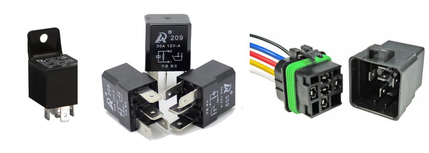
These are some of the typical relay styles you might find in a car or project car. Their are more styles then this, however these are most common and find their way into many aftermarket projects and builds. Far left is the most common of all the square style (mini or standard). This may or may not have a tab for mounting. These are very popular for aftermarket applications due to low cost, high power capability and easy to buy.
Next in the middle is a bit newer style that has high capacity as well, but comes in a much smaller package (Micro). I have used these in the Sunbeam Tiger Dash project.
Last one we will look at is the waterproof relay. It's basically the same as the old standard square relay but comes with a special housing and connector to keep it dry.
Any relay you have will have a couple of parameters that define its capacity. Typically that will be operating voltage and maximum switching current. For example, the middle relay above (Micro style) shows that is has a maximum capacity of 30 Amps, and it operates at 12 Volts. It's important to respect these ratings, and make sure you are using the correct relays for your application. Another words, don't use a 24 Volt relay in a 12 Volt application. Make sure also you do not exceed the maximum current capacity of the relay. It's often a good idea to keep the current well below what the maximum rating is for relay longevity.
Automotive Relay Sockets
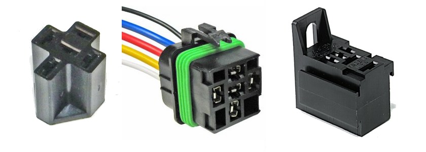
Somehow you will need to connect up your relay to the wires. You can do it many ways, but the best way is to use a socket for the specific relay style. Mini and Micro relays use different sockets.
The relay socket on the left if for the typical square relay, socket in the middle is for a water proof relay, and finally the socket on the right is for the now popular Micro-relay style.
Sometimes these come pre-made with leads and connectors, other will come with connectors and you need to crimp the wires and assembled. It's pretty easy to do. If you noticed, the connections to the relay are regular spade connectors and if you don't have a socket you can use simple terminals if you are in a jam.
One note of caution is be very aware of the wire gauge. Some of the imported and super low cost sockets come with wires that are well under rated for how much current the relay can switch. The coil or control of the relay can have thin wires, however the switch part of the relay should have very thick wire. The el-cheep-o's have a nice thick wire, but when you strip it down it's not very thick at all. Uses these with caution on high loads.
I prefer to make my own connections, if you do, you can find these type of sockets most anywhere, and in many different configurations including multiple ganged, etc.
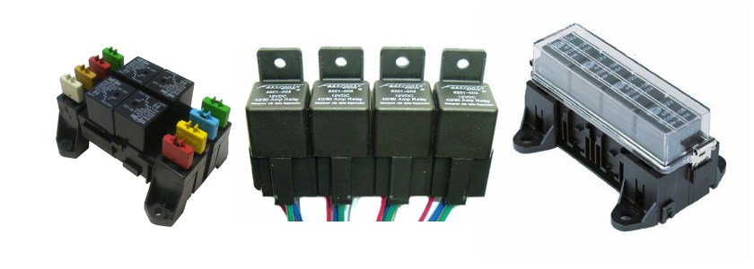
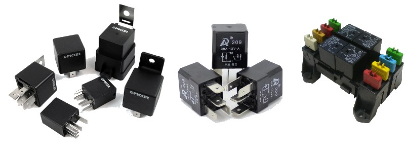
Ganged Relay Sockets
I mentioned you can get the socket in many styles, above are a few that you will find in after market applications. The most typical is the one in the middle. This style is a bunch of sockets that slide together. I'm not a huge fan of these style since it's difficult to swap out one relay since all the sockets are interconnected or you have to unscrew something. Still a simple and low cost way to mount the relays. The relay block on the left is a more integrated approach since it has built in fuses for each of the relays. These can be had in many relay counts and styles. And finally on the right is another version from Hella that has no fuses and a nice cover to protect it. These are sometimes called relay boxes.
Standard (DIN, BOSCH, ETC) Relay Wiring
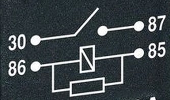
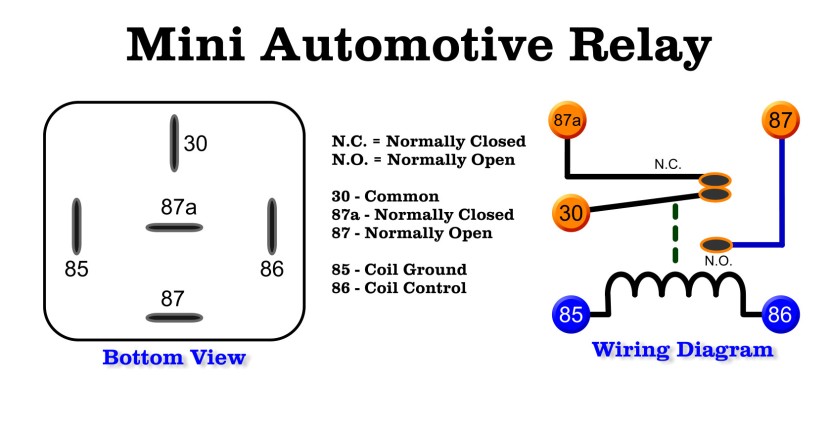
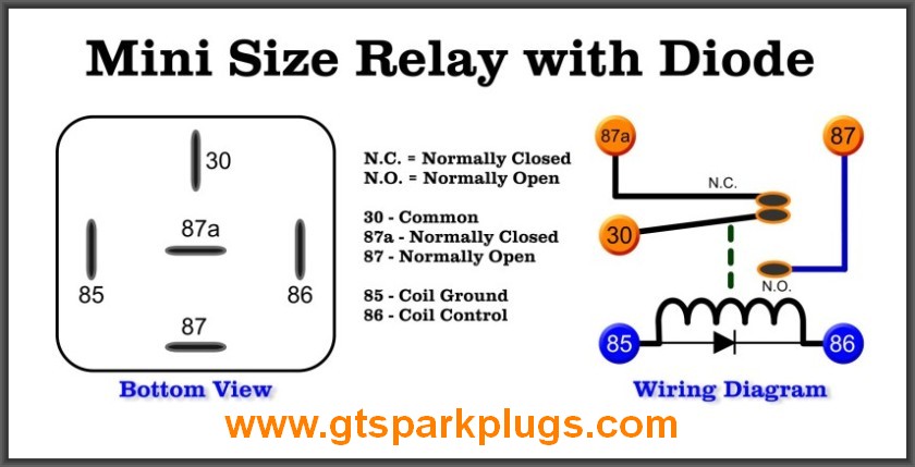
Here is the wiring diagram (pin outs) for the typical square relay. Each of the connections has a number. Each number has special meaning to help keep the wiring consistent, thank the European folks for that nice feature. The electrical numbering convention comes from the DIN 72552 spec (use the web).
So the connections are defined as follows -
85 - Relay's Coil Ground
86 - Relay's Coil Control Voltage (typically +12)
30 - Switched Common
87 - Switched Normally Open (Relay not powered, contact open)
87a - Switched Normally Closed (Relay not powered, contact close)
And just to make sure you have it straight when you apply power to the relay across pins 85 and 86 The relay will close and contacts 30 and 87 will connect, contact 87a will now be open. NOTE : Many relays do NOT have the 87a terminal so if you need a Normally closed contact make sure you see 5 connectors on the relay. This is true of the Micro relay as well. Later on I'll show a very simple diagram of how it's all wired up.
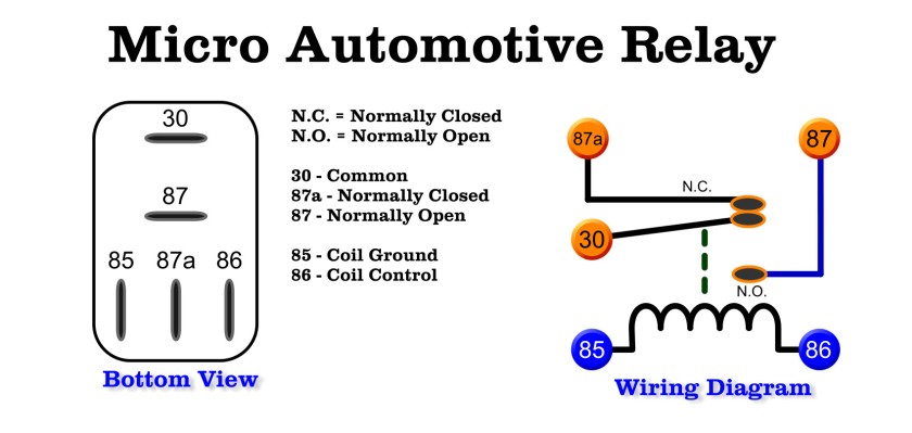
Standard Micro Size Relay Wiring
Other then the shape and size of the relay, the Micro and Mini relays have exactly the same functionality. The connection number are exactly the same as the regular square (DIN, Bosch) style relay. About the only difference is that you can get a higher current capacity in the Mini (standard) style relay.
How to Wire a Relay
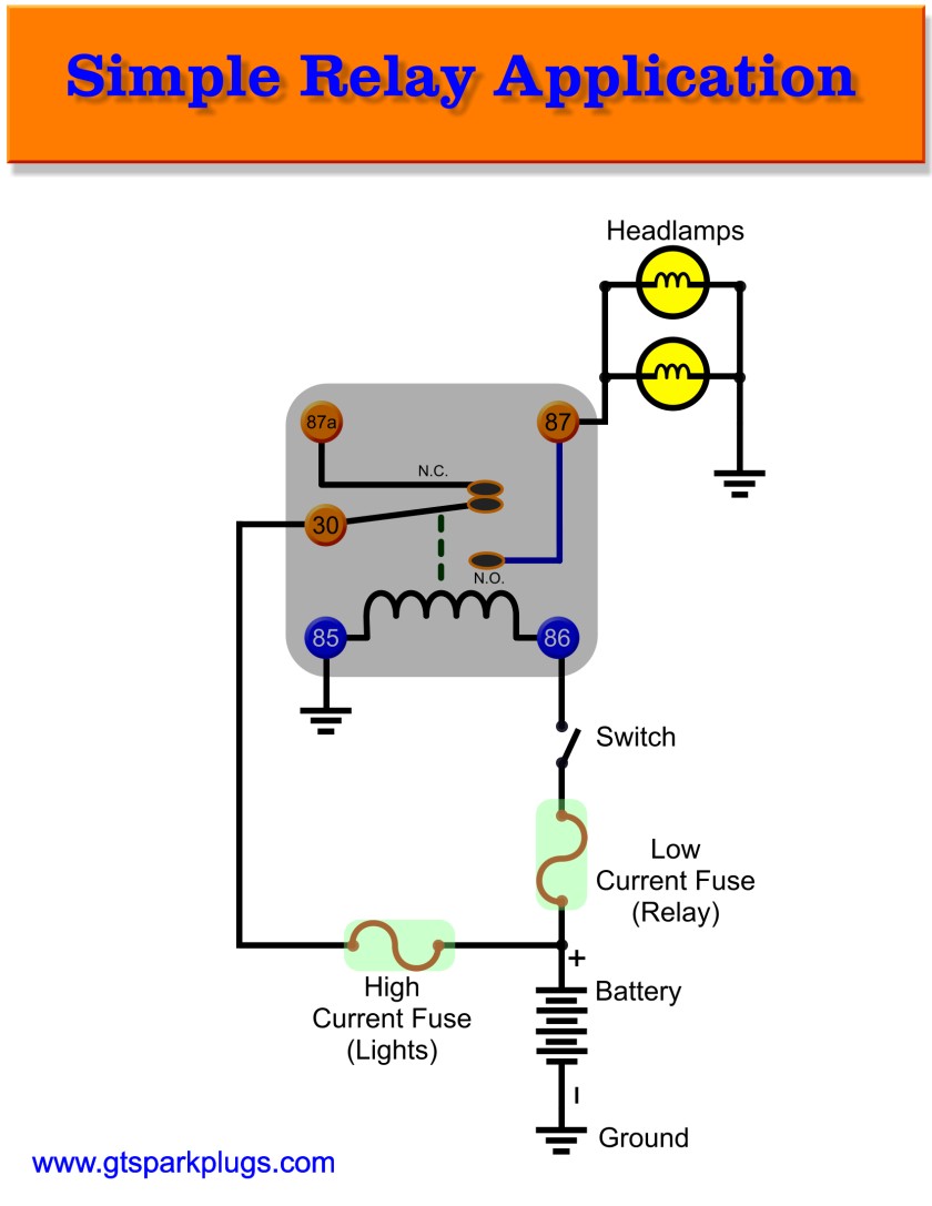
Here's a very simple sample. In the example above you can see a few things going on. First and foremost you should always have a fuse(s) in your circuit. One thing that is often omitted is a SECOND lower amp fuse for the relay itself. It's also important to protect the relay and wiring to it. Either Mini or Micro relay can be used. In this example we are working with fog lights, but could just as easily be an air horn, or cooling fans.
This is the most basic circuit for using a relay. In this example I want to hook up a couple of bad a$$ed fog lights to my Excursion. These lights draw a lot of current, in the order of 30 Amps when on. This would be a lot to switch with a small toggle switch that I can fit into my dash. So what I will do is... Yes you guessed it, use a relay.
In the example above think of the Ground as wire that connects all grounds up.
The battery provides power for the lights and the relay, and the fuse protect the wiring in the event of a short circuit.
Now what happens is when I flip the switch I expect my flame thrower fog lights to come on. How this all happens is as follows -
The voltage can't get to the fog lights since the relay circuit is open. Terminals 30 and 87 need to connect before the lights will go on. The way to do this is provide a `control` voltage to the relay. When the switch is closed terminal 86 gets powered up and voltage goes though the relays coil. The other end of the coil, terminal 85 is connected to ground. The circuit is complete and the relay will PULL the contact down opening terminal 87a (if it exists, it's an optional connection remember) and closing to terminal 87. Once that happens the current can flow from terminal 30 right to terminal 87 which connects finally to the bulbs. The circuit is complete as the other side of the bulbs go to ground.
IMPORTANT NOTE: You should generally wire terminal 85 to ground (or switching to ground) and positive control voltage to terminal 86. The reason is that if you use a relay with a built in Diode it will burn out the diode and possibly a fuse. It's good practice to do this even though a relay without the diode will work either way.
If it helps, think of the wires a bit like plumbing pipe.
If you want now shut off the fog lights you only need to break the connection by opening the switch and the process reverts back to the off state.
Remember it's important to use the proper gauge wiring for you application. If you need help with that look at the Wire Size Calculator for help. In the simplest terms, larger gauge for heaver loads and larger gauge for longer wires.
Hope this helps, and again click the little spark plug in the title if you have questions.
Introduction to Relays Conclusion
Let's wrap this up. We learned a few things about styles and how to hook up the basic automotive relay. Remember a few things to keep you on track, and that is correct parts for the job! Wire size is very important as well as the often forgotten fuses. Hopefully the How To Wire a Relay has helped you understand the basics of how to get it done!
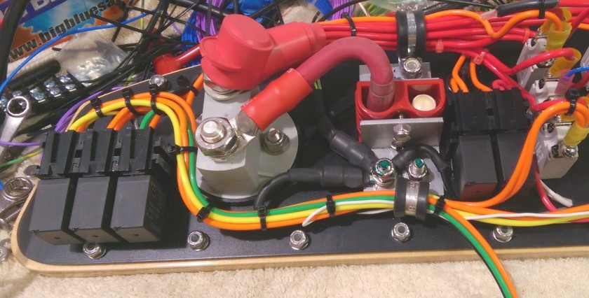
Above is an image for my Sunbeam Tiger dash where I have crammed a lot of stuff on the back side. You can see a total of 5 Micro-Relays crammed into the back of the panel. These are a nice alternative to the full size square ice cubes you often see.
Happy Motoring!
Relays with Diodes and Resistors
If you carefully look at the diagram above you will see an odd triangle thingy under the coil of the relay. This connects to pin 85 and 86. (larger white image)
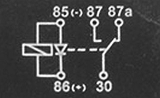
Looking right below that you will see 2 smaller black images with a close up of the relays with the diode or resistor suppression functionality. If you have a relay with one of these markings it should be replaced with the same type. These relays are designed to prevent voltage spikes and glitches from entering back into the system.
Picture on the left is a Diode relay, these are generally better at stopping electrical noise from the relay coil. Notice the fuzzy (-) and (+) near pins 85 and 86.
Picture on the right is the Resistor relay, it has a simple resistor across the coil. Sometimes may be pictured with a zig-zag of lines.
These relays to help keep noise and voltage spikes out of the electrical system. Relays controlled by the EMS (ECU, Computer, etc) are more sensitive to the electrical spike that is introduced by the relay opening. The job of the Diode (or sometimes resistor) is to suppress this voltage spike.
As mentioned above it's important to always make pin 85 the grounding pin and pin 86 the control voltage pin. If you don't the diode will blow (even though relay may actually still work).
These relays are generally interchangeable with the standard relays unless someone wired things incorrectly. The other way is not really true, If you replace one of the suppression type of relays with a standard non-suppressing version it may work, but it's not recommended and could ultimatly damage something or lead to erratic operation.
