Speedhut Warning Light Controller
I had a custom set of gauges made by Speedhut for my Sunbeam Tiger. My dash already has a couple of LED lamps that I wanted to used as a low oil warning. The oil warning lamps are truck side markers that use a single bright LED lamp. After a quick call to Speedhut they said I can't do it and would need to use one of their simple LED external warning lamps. It's not that I don't like the Fast and Furious look, but I already had a nice ugly couple of lights that would do the trick and didn't yet need more do-dads in the cockpit.
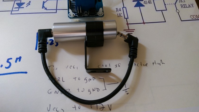
So on my quest to DIY the interface to the Speedhut gauges (only some have the external warning lamp jack), I picked up their warning lamp. Was about $35 bucks shipped, came with a cable and a mounting clamp. The size of the lamp is about the size of a lipstick tube.
That all being said, I proceeded to open it up. It's very simple, basically you connect it up with a stereo 1/8" earphone jack, and it has 3 wires, one for control, one for power and the ground. The basic idea is that the control drives a transistor that turns on the 4 LEDs that are on the board.
At this point I also decided that I would like to drive a Relay from the warning output, which has a much wider application the a lamp drive. For example if the temperature gauge hits a certain temperature you could use the output to turn on a fan, etc.
Long and short of it, I did both diy projects. I likely will only use the LED controller that was modified from their warning light, but I went ahead and tested a relay controller as well.
The Speedhut boys (and ladies) are slick, when I tested the warning light I noticed that it also follows the setting for the internal warning light (it's dimmable). ALSO when you have the dash lights on, the warning lamp will also dim down. Very nice, this works well with the LEDs, but not quite so good with the relay module.
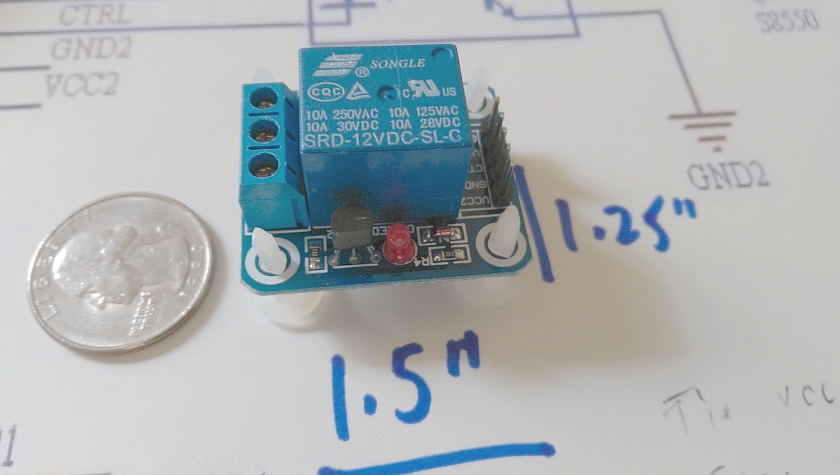
I picked up the Relay module off of eBay. Shipped cost from China was about $4. They have similar on Amazon (some are not opto-isolated). They make them in 1 to 8 relay modules and some are opto-isolated to provide more isolation between the controller and relay module. Just make sure that you get a 12 VOLT board, many are 5 Volt and that will not work. Different boards will have a potentially different hook up.
And remember do this at your own risk, if you are not comfortable with electronics, don't do it, if you can't solder, don't do it, if you think you can blame me for blowing out your gauges, really don't do it.
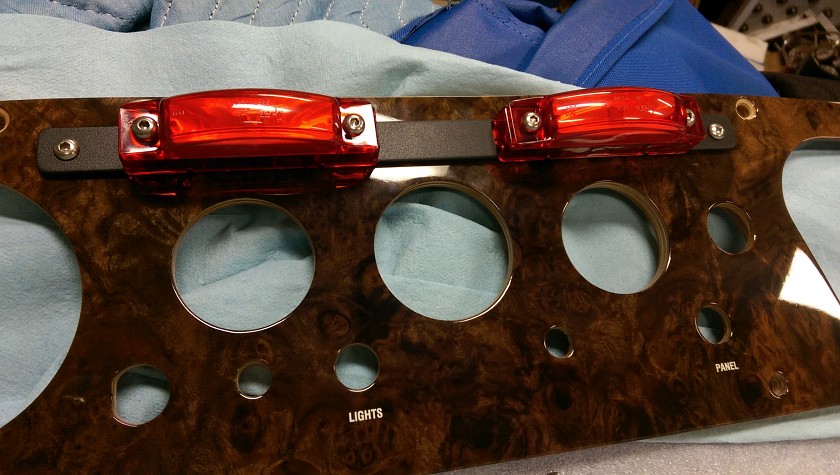
External Oil Warning LEDs
This is my modification to hide the heater slots (not using a heater) and make sure I see the oil warning if something goes wrong.
Speedhut Shift Light (or Warning Light)
This is the Speedhut shift light. It's also called a warning light, or shift light. It's about the size of a lipstick tube, and it's all held together from the back with the small nut that holds the earphone jack to the case. Unscrew this little serrated nut with a small needle nose pliers and the hole assembly should pull right out. Note that I ordered the shortest cable. Order the longer ones (they are the same price), this may help down the road.
NOTE: Speedhut make several models, just make sure you get the super cheep one, the others are very different and have more advanced electronics and features.
Guts of the Shift Light... Oops I mean Warning Light
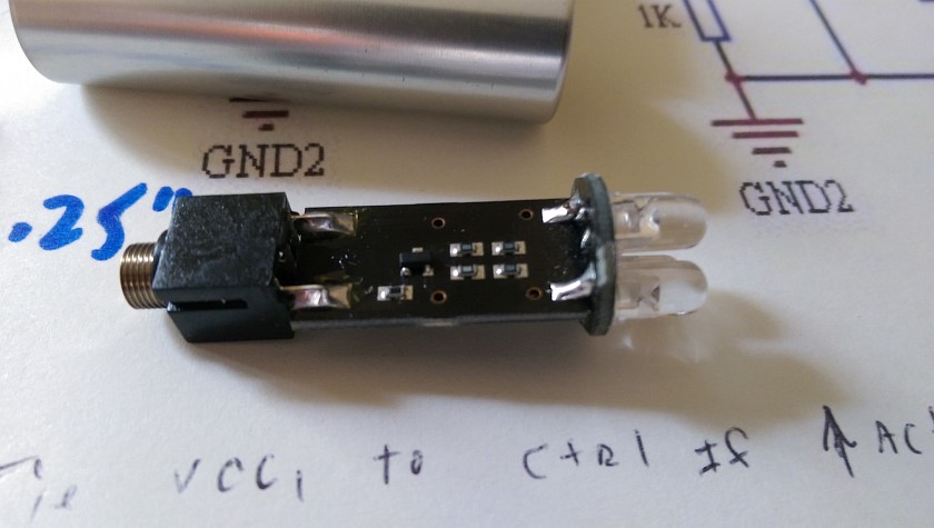
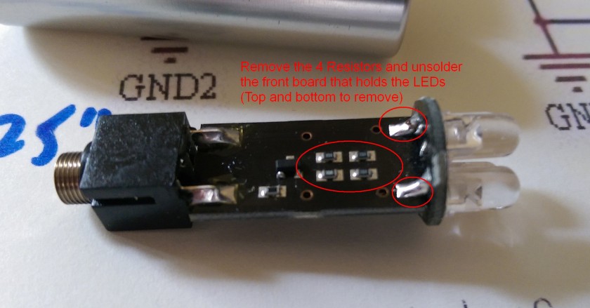
After sliding out the circuit board this is what you see. This is the top of the board and it really has 5 resistors, a transistor and 4 LEDs. Nothing too complicated, circuit is simple enough that their is no reason to post it.
Time for the Soldering Iron
Time to get busy. Since I'm not going to use the LEDs the front assembly needs to come off. The small round board holding the LEDs is soldered on the top and bottom of the board, so you will have to move fast to heat all 4 joints up to remove the board.
Once the board is off, now hit the 4 resistors in the read oval. These are not going to be used in my case.
Why?
Well as I mentioned my LEDs are for a side marker for a truck, given that, they already have build in resistors to deal with the 12 Volts.
IF you are just driving remote LED's they you will need some form of resistor depending on your LEDs configuration and current rating. Look here for some help on the dropping resistor value and how to calculate it.
Attach External Wires to Circuit Board
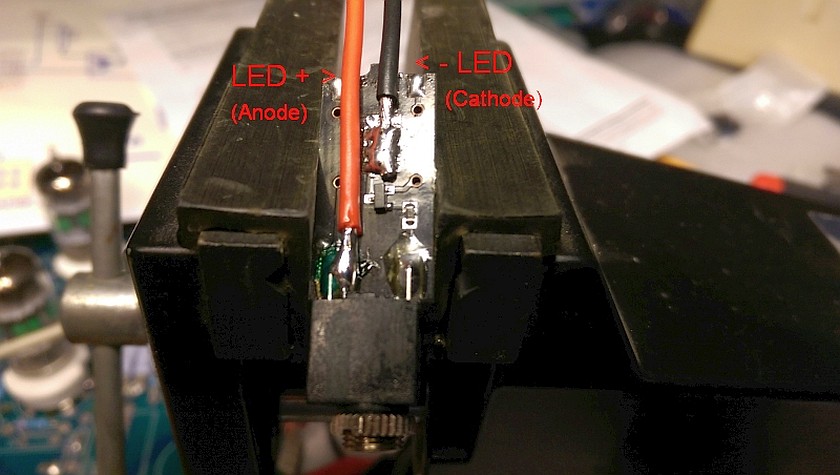
Get some thin wires (preferably different colors!) and attach the wires as shown. The Red wire can attach right to the back of the earphone jack (I colored that connection GREEN). This is the POSITIVE wire.
Now were you removed all 4 of the surface mount resistors solder you wire so it has a good blob of solder and the wire is solidly mounted as shown. The idea for using all pads is to make a good strong place for the wire to hold on to. Use a thin and flexible wire, mine are a bit on the large side.
Watch out for the transistor (3 legged thing betweend the red and black wires)
That's about it.
Finishing Touches to the Controller
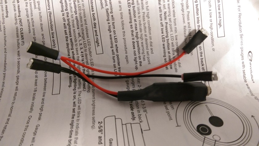
After testing (this is a good idea) I used some large heat shrink tubing to cover the PCB. Then crimped my needed connectors as I have 2 lights. Remember my lights are for 12 Volts. This now can plug into any of the Speedhut gauge and drive my external lights. Remember only some of the gauges have the external warning light jack.
NOTE : The Speedhut controller ONLY DRIVE LED BULBS, it does not have enough current to safely drive regular incandecant bulbs as they draw too much current.
Relay Module
This is the relay module I picked up from eBay. It was only a few bucks and has the bonus of being opto-isolated if you care. Again make sure your module is 12 volts! The idea here is use a $5 module instead of taking apart a $30 shift light for the controller. These relays are often used with small computers, raspberry Pi, etc to control larger loads or even larger relays. I had pulled off the small connector on the right as it seemed unnecessary since I was soldering wires right to the board. Do the same if you want, same for the larger connector on the left which I'm not a fan of that style connector.
Speedhut Shift Light Plug Wiring
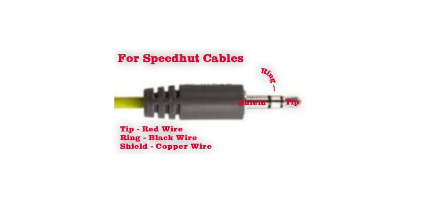
This is the wiring diagram to the plug. You can use other cables (computer speaker cables, etc) but the wiring colors likely will be different. Use your Ohm Meter to match things up.
Relay Module Schematic
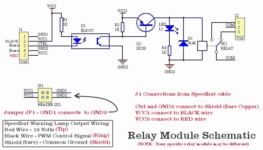
Here is the schematic that was supplied with the 12 Volt relay module. It was designed to be flexible and as such more complicated to make work. To connect up the Speedhut gauge to the module you need to connect the wires of the Speedhut cable as shown. Black Wire to VCC1, Red Wire to VCC2, Bare Wire to CTRL _AND_ GND2.
Once that is done you need to put a jumper across G1 to G2 (GND1 to GND2). I just squeezed the pins together and soldered them. No reason to have a removable jumper that could come off.
If your board doesn't have an opto-isolator you may have a simpler set up. The control to the input of your board will be the BLACK wire, the Ground will be the BARE wire and the input voltage will be the RED wire. Hope you can figure it out.
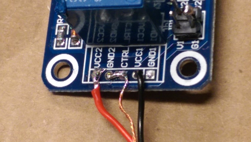
Relay Module Connected
Here you can see the wiring and how I blobed it all together. The other end of the cord is the 1/8" mini-jack that plugs right into the back of the gauge (I used a Speedhut cable that I cut one end off). After testing it works great except for one issue.
Since the output of the warning light from the gauge has the feature that it can be dimmed, it can be a problem in driving the relay. I tried the set up and it worked in all settings except the dimmest.
NOTE: IF you have your gauge set to have the warning light on full brightness it will work fine with the possible exception that if you have your gauge lamps on. Turning on the gauge lamps causes an automatic dimming of the warning light regardless of the setting. It's advisable to ensure the relay will still operate with the gauge lamps activated.
It's now up to you to insulate and mount the relay. Connect up anything you might want to the relay that is within it's current rating specs. In this case I would keep things under well 10 amps, if you need more use this relay to drive another relay...
Speedhut Relay Interface - Switches High Current


