DIY Foot Switch
In my quest to build a roll cage for my Sunbeam Tiger, I ordered a bunch of Docol R8 tubing. Finding out that dealing with 20 foot lengths is a pain, and that I would not be able to use the saws that I have deep in my garage I decided to just get a Dewalt Portable Band Saw band saw. In thinking ahead I also picked up a Swag Offroad table mount for it as well. They offered a foot switch which is a good idea, but I had seen one of these super duty looking ones a while back from TEMCo Industrial (Imported stuff), it was really nice looking, metal, but it needed to be wired up. Here is that simple project.
Parts
TEMCo Foot Switch from Amazon
Wiring Terminals for attaching wires to switch
Wire Nuts
Extension Cord - I used an old cord I had to save a few buck
Tools needed
Wire Cutters/Strippers
Screw Driver
CAUTION - PROJECT INVOLVES ELECTRICTY AND RISK OF SHOCK
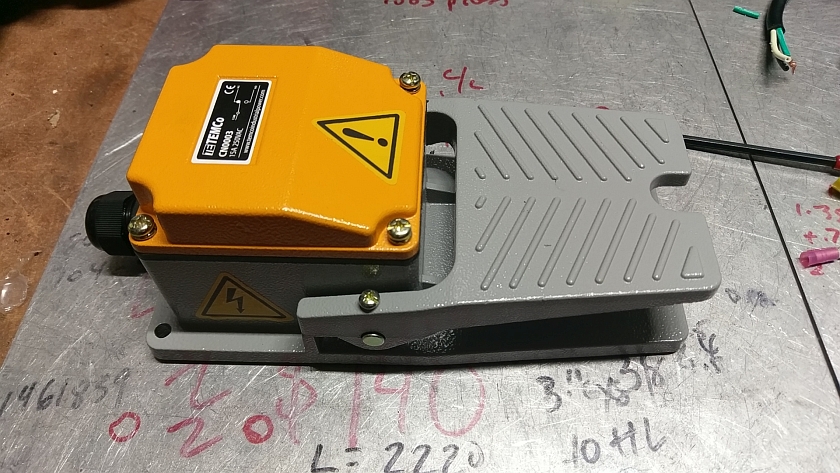
TEMCo Heavy Duty Foot Switch CN0003
This is how it arrived. It came with gaskets and a nice rubber base. It seems to be made of aluminum casting and is very nicely finished. It even came with the cord strain relief on the back. Cost was about $16 bucks. I was not expecting it to be this nice!
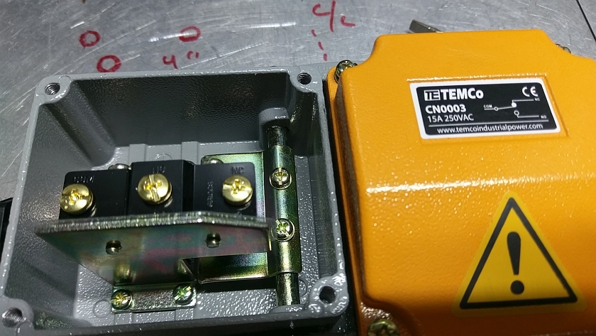
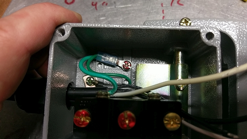
Inside the TEMCo Foot Switch
After removing the cover and gasket you can see the simple mechanism and switch. The switch is a SPDT (Single pole, double throw) rated at amps: 15A/250VAC. Again nice finish on the inside. Note while it does come with a gasket for the lid I would not call it totally water proof since the cross bar doesn't seem to have any seals. But who cares, it for my garage.
Wiring Terminals
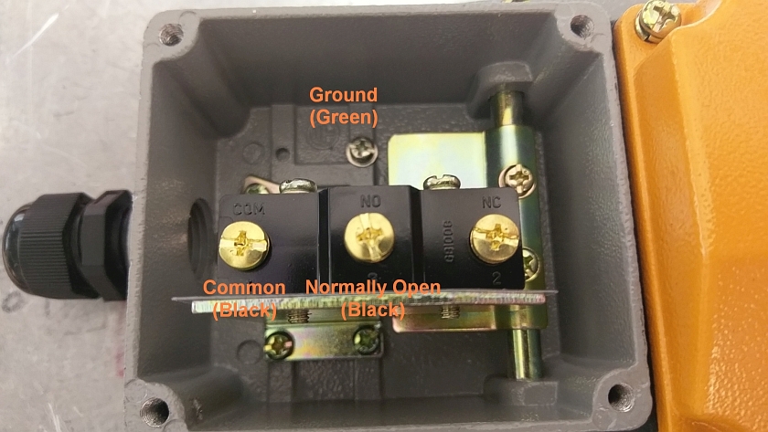
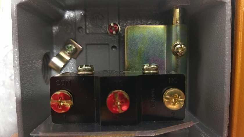
Here is the layout of important terminals in the foot switch. The 'NC' terminal is NOT used. If you are not using a grounded cord that's on you, but if you do make sure you scrape the paint below the screw for the ground wire. Below is the wiring diagram to help out a bit.
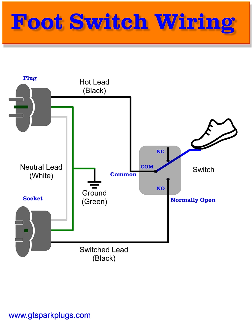
Foot Switch Wiring Diagram
Above is a simple diagram that shows how things get wired. I used an old extension cord and cut a short piece for the socket side. The wiring colors in the USA are BLACK for HOT, WHITE for NEUTRAL and GREEN (or GREEN/YELLOW) for GROUND. As the wiring shows we are really only wiring the BLACK wires to the switch. The WHITE wires go together and the GREENS as well. The GREEN wires go together and also to the screw into the case.
Strip Back Wires
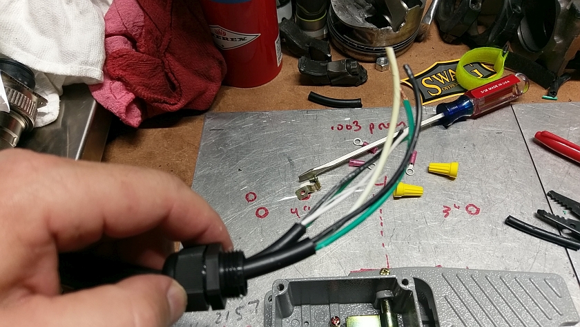
Using the supplied wire strain relief loosen it up and wedge both wires through. Hopefully it's a tight fit or the strain relief isn't going to do much. You should strip back the outer wire covering so you have a bunch of wire to work with.
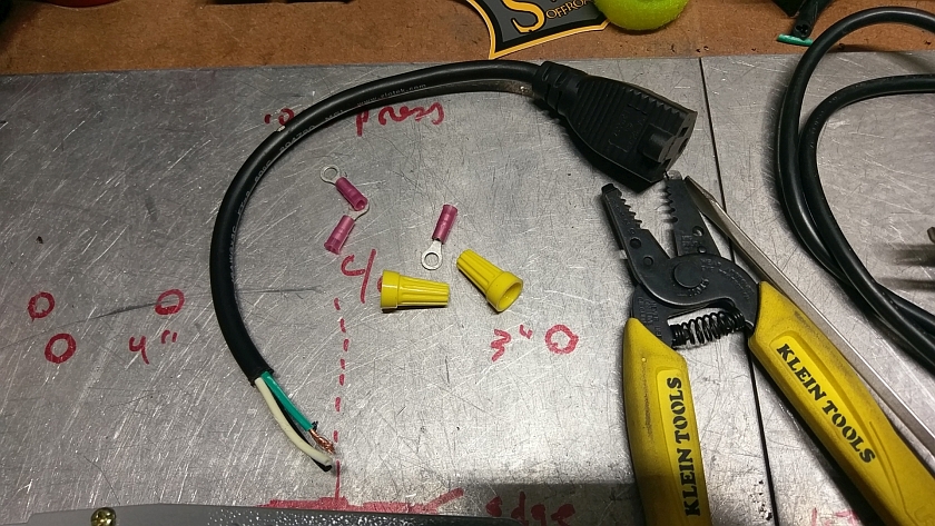
Collection of Wiring Parts
Here is what I used to make it safe. I crimped on some ring connectors to the BLACK wires and to the GREEN wires. And for the WHITE I used a common Wire Nut. That's about it.
Clamp Wires
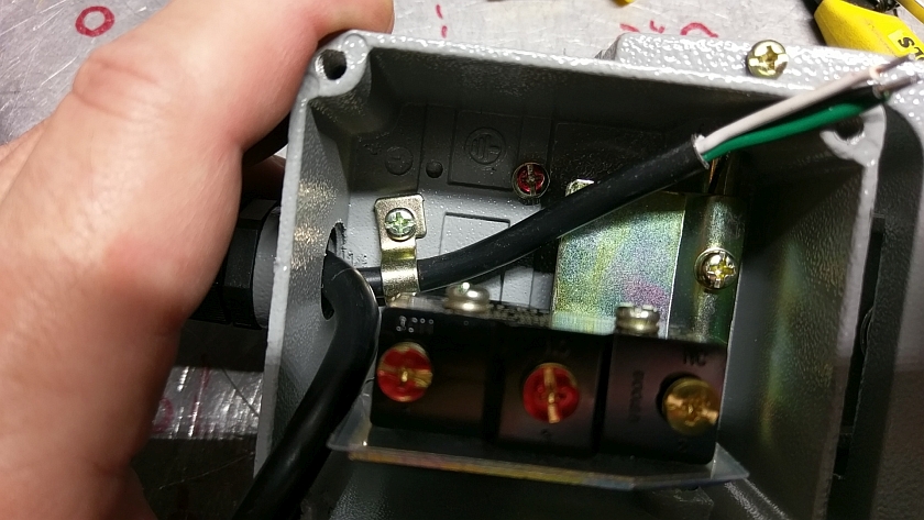
Well Wire, the internal clamp can grab one of the wires, so I did it to the side with the plug. ONLY use this over the outer sheath of the cable not the individual wires.
Switch Terminals Marked
To make it EZ I marked the terminals of interest in RED. The small screw in the bottom of the case is the GROUND, and will connect to BOTH GREEN wires. The BLACK wires, one each, will go to the switches terminals as marked in red. Doesn't really matter which goes where, but if you are concerned the HOT from the plug can go to the COMMON (COM) on the switch.
Safety First - Ground Wires
Connect BOTH GREEN wires in a ring terminal and screw onto the base. Again, make sure you scrape the paint clean under the terminal to ensure a good ground connection to the foot switch.
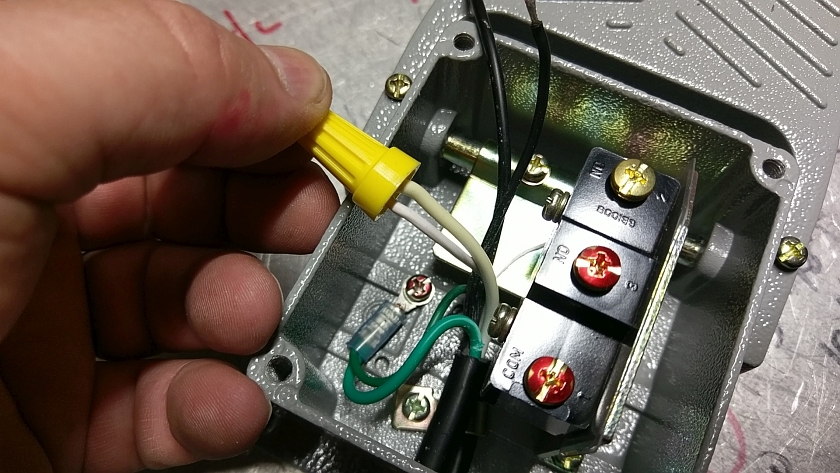
Neutral Wires - WHITE
Both of the cords WHITE wires need to be connected together. I just used a good quality wire nut.
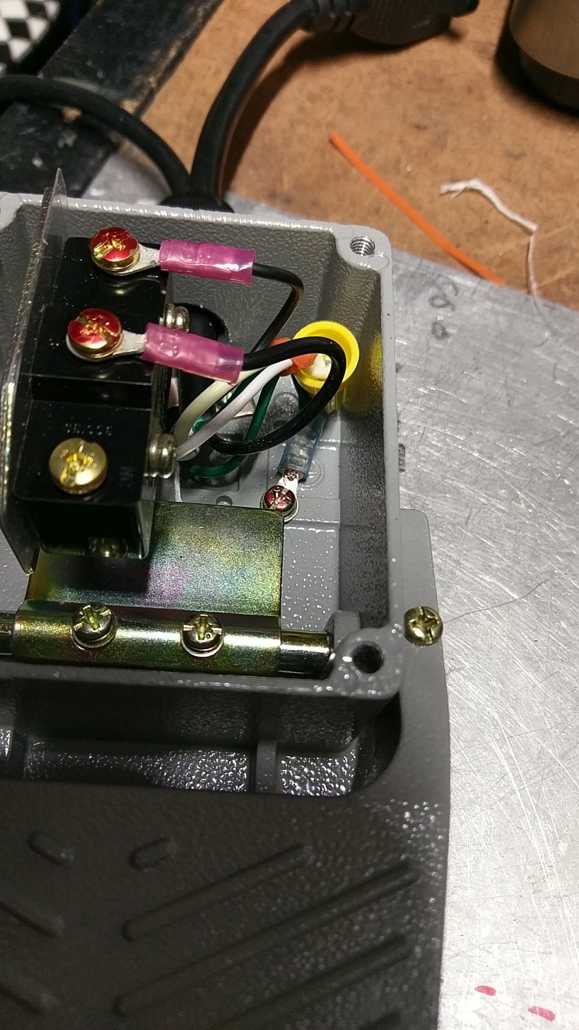
Final Switch Wiring - BLACK Wires
After you crimp on some ring terminals to the black leads (cut to length) you can screw them down on the switch. Again you can wire the leads up to either terminal, but if you are a stickler you can wire the incoming power (From the plug) to the terminal marked COM. Make sure none of the moving parts rub the wires, you may need to use a tywrap to pull them together to ensure this.
Go For Launch
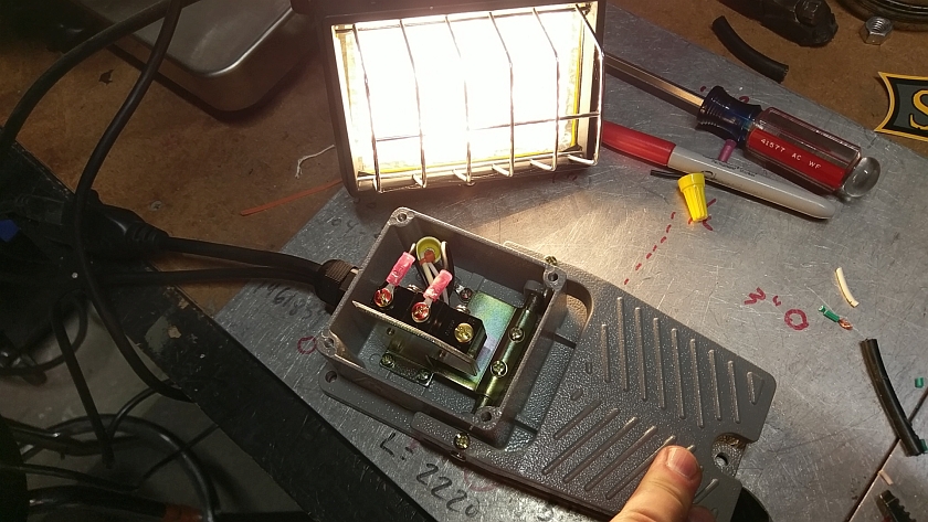
Before putting it together time for a test.
CAUTION CAUTION CAUTION CAUTION
With the lid open you can be exposed to dangerous voltage. BE CAREFUL AND DO NOT TOUCH ANY EXPOSED WIRES OR TERMINALS
CAUTION CAUTION CAUTION CAUTION
Plug in the foot switch, plug a light or something safe (Not a saw...) and see if it works. If not, re-read the above. If you blew a breaker re-read the above.
If the light comes on (In my case) you are good! UNPLUG the unit from the wall and put the lid back on. That's about it. This is a simple DIY project that has many uses. Just remember that the maximum current the switch can carry is 15 AMPS or less.
Happy Motoring and GET them projects done!
