Drive Shaft Angles - Vibration and Velocity
This is a DIY, need to fill out the discussion on why each is bad, but you can start with the `EZ Read` diagram below. In addition to the traditional drive shaft vibration images we discuss (as in the royal we) a bit more why this happens and show some examples of what's causing the vibrations.
It's pretty simple, but sometimes hard to figure out the angles without a few simple tools. I did this for the Sunbeam Tiger axle swap and used a digital protractor that really made things easier. If you are diagnosing problems look for things like bad engine or transmission mounts changing the angle of your driveline, also look at obvious damaged U-Joints, lack of grease or extreme use can destroy them pretty quickly if not maintained. As an example I had an old International Scout 2, after mud womping and having the truck pretty much submersed I ran into a vibration from the driveshaft. Figured I broke something. Ended up the seals were bad on the U-Joints and water soaked into them and rusted out the needle bearings due to lack of grease. New U-Joint and I was back in business. So the idea I want to say is look for improper angles, something that might have changed that caused the vibrations, or failed components. Their is a lot of details on the web from some very smart driveline folks, it's definitely worth a read if you have more interest.
The type of vehicle and use can also impact how your drive shaft(s) are set up. Drag racing may be set up very different than road racing as is Off Roading. Their are many, and I mean many different ways to set up a drive line, different styles of U-Joints, CV Joints (Constant Velocity), and more. I'll limit discussion to the old school U-Joint and drive shaft.
So here is an introduction to drive shaft angles, universal joints (U-Joints) and related. Some of it is pretty simple, and some is more complicated, but the idea here is to make this a bit easier to follow with less complex discussion and clear EZ Read pictures.
Again if you find Errors and or Omissions that you think are worth mentioning PLEASE drop me a note by clicking the Spark Plug in the upper right corner of the page. This is still a work-in-progress!
Typical Drive Shaft Angles and Vibrations
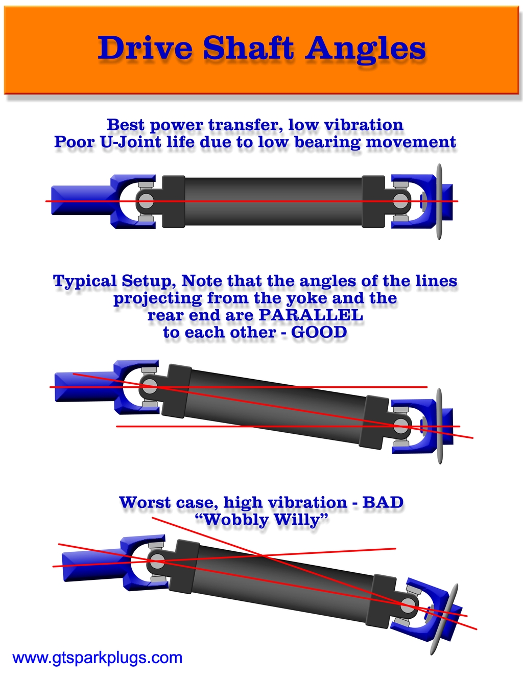
The above picture shows some typical set up for drive shafts. Their are a few types of set ups, straight, parallel and wobbly willy. Each has different vibration characteristics. You can find a million of these by doing a google search. But we must start with this as it's the most commonly overlooked thing when setting up a new driveline.
Here Ya' Go -
The straight shaft has the least vibrations, but it suffers a different problem. Since the U-Joint never moves as the shaft spins, the needle bearings never move and can tend to be under lubricated and get work hardened. Keep an eye on the red lines that are shown. In this case their is only one red line since everything is on the same plane.
The Middle 'Shaft' represents the best case scenario. The key things to note is that the angle of the tail shaft from the transmission should compliment the angle of the differentials input by the same amount. This is the key to vibration free running. The idea is that the angles of the input and output U-Joints will cancel out any velocity changes in the shaft and keep things from vibrating. More explanations of this below. Another important aspect of the middle image is how the 2 red lines projecting off the yoke and the diff would be parallel. This is the desired way for the angles to be. Also a consideration is the overall angle will have some affect on vibrations, the less the better obviously.
The Last image ("Wobbly Willy") is one of many worse case scenarios. Since the angles are different from the input yoke to the output each will have it's own velocity, and they won't effectively cancel out the differences in how the shaft spins. Look onwards for more info, but if you have a drive shaft set up like this, expect vibrations. If you look at the red projection lines you can see how they are not parallel. This is a problem and causes the drive shaft to vibrate since the U-Joints are not at complementary angles.
Also note that as the overall angle increases (Like on lifted 4X4's) you can run into issues. Their are many specific solutions to this problem, but that's left to you to find on the off road sites.
Drive Shaft Velocity
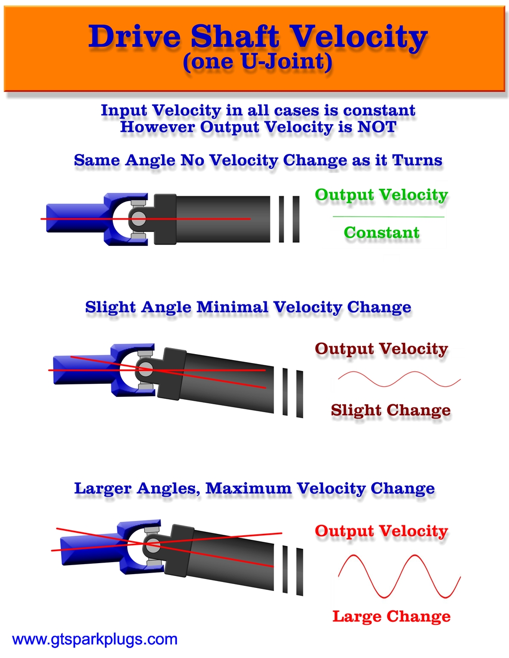
Ok so you got past the pictures of good and bad drive shafts, but want to know more. Well it's pretty simple, that is until you do some of the complex math. Similar to the first set of drive shaft images, we are now going to look at just half of the drive shaft, that is, only one U-Joint connected to a shaft.
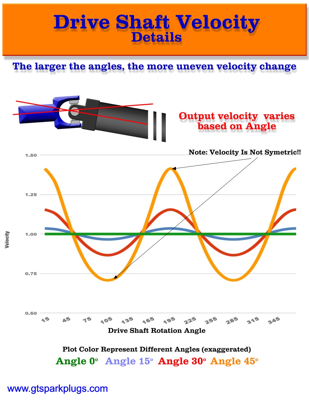
The velocity is loosely defined as the speed of the rotation of the shaft. You might think that it's constant, but it's not except in odd cases. The change in velocity is what causes vibrations. Read on my curious friend...
The first one should be pretty obvious, as the input spins the output spins the output velocity will be constant. The U-Joint has no affect on the velocity as it rotates.
The Second we add a little angle between the yoke and the drive shaft. As we can see the Output Velocity is NOT constant. It will speed up and slow down over one complete revolution of the shaft.
The Third Example is even more angle and as you increase the angle the change in velocity between fast and slow is even greater.
NOTE : That the simple pictures of the Output Velocity wave don't really reflect it as accurately as it is in real life (or mathematically for that matter). The waveforms are not symmetrical, that is, the drive shaft speeds up different than it slows down. This makes things more complex in removing vibrations as the angles of the input and output differ.
Incorrectly Built Drive Shaft (Out of Phase)
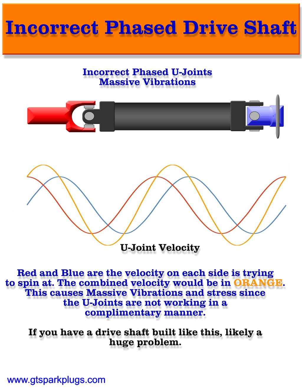
Well in the case above it would not have any vibrations, why...
Think about the discussion on angles of the U-Joint. But the main issue is the phasing of the U-Joints. The are twisted 90 degrees from each other. This causes very extreme velocity changes that are not cancelled out but the opposite U-Joints. So if the forks of the U-Joint look like this it's wrong and your 'shaft' will vibrate.
Poke around on YouTube for an old Spicer video that show this and a lot more on the velocity and phasing of U-Joints.
So it's important to make sure that both ends of the drive shaft are in-sync and aligned properly.
Drive Shaft Rotational Velocity
As the angle of the joint changes you can see how the velocity changes. It is not symmetric! The values in the chart above show 0-45 degree examples. While these angles are greater exaggerated, and larger than practical used, they show how fast the drive shaft will spin given a particular angle of rotation. The speed differences between fast and slow are still at play if ANY angle is present.
Remember we are still looking at ONE SIDE of the drive shaft assembly for now.
So just to be sure you get this, the constant input speed will not have a constant output speed after a U-Joint with some angle in it. If you want to see this get 2 longer socket wrench extensions add a swivel in the middle (Yes, it's a U-Joint), and twist is while flat. Twist it while at some larger angles and see if you can notice the speed difference.
CAUTION DRIVE SHAFT MATH AHEAD
Here is the formula for those that are not math challenged. The InputSpeed will be taken as a constant. The RotationAngle is the angle of the drive shaft as it spin through one cycle, and finally the InputAngle which is the angle between the input and the drive shaft. This info came from Wikipedia of course, but it's likely also sourced in some of the more complex automotive engineering books.
InputSpeed = 1 (A constant Speed)
RotationAngle = 0 - 360 degrees
InputAngle = Angle of the Input to Drive Shaft
Velocity = (InputSpeed * cos(InputAngle))/(1 - (pow(sin(InputAngle), 2) * (pow(cos(RotationAngle),2))))
Drive Shaft with Cancelled Vibrations
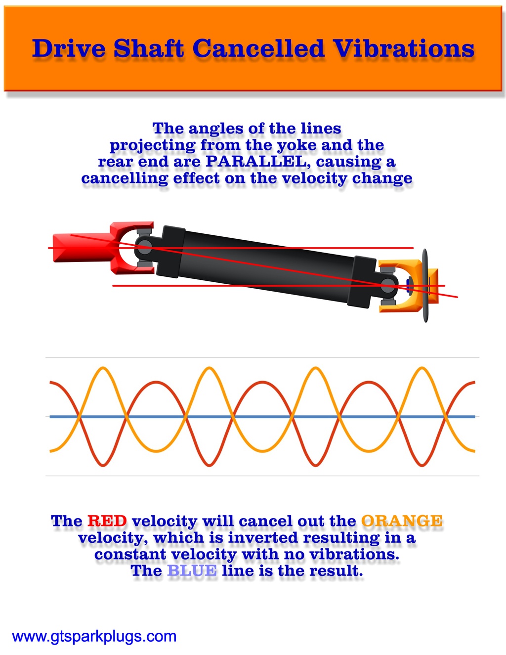
Ok, so it's taken some time to get here, and you likely could have guessed the results. When a drive shaft is set up with the input and output angles correct you will have no vibrations. The idea is that they run at inverted velocities and cancel the effects out of each other. As you can see from the EZ Read chart above the Red and the Orange velocities are opposite. This means that the net effect of velocity change is 0 (The BLUE line).
Many things can affect vibrations to be sure, angles, balancing, length, RPM, load and a host of physics that I won't pretend to understand.
The Wrap Up
Not sure if I should say no pun intended, but... Ok I won't. But their are many important factors to keep your drive shaft and U-Joints operating properly. Best course of action is to ensure all equipment is in good shape (no dents or scrapes), needle bearing haven't fallen out, balancing weights (sometimes just a washer) are still where they are supposed to be, and your angles of the driveline have not changes to the point of violating the basic rules outlined above. One tool that I did find very useful was the digital protractor. I have used this for bending tubing, and drive shaft angles, very hand Digital Protractor from Amazon it is magnetic and surprisingly easy to use.
Sunbeam Tiger Fun Fact -
The Sunbeam Tiger the drive shaft is not only angled downwards to the rear axle but also offset. So unless the engine is put in the car cockeyed, their will be no way to eliminate vibrations by canceling out the offset angle. The saving grace is that the drive shaft is so short it's not noticeable at speed.
Happy and vibration free motoring!
