Ford Motor Mount Strengthening
If you have to use the stock early Mustang (65-66 possibly other years) motor mounts and can't or don't want
to use the urethane aftermarket mounts. This technique may work on other style mounts with some
modifications. This modification has been done for many years by the Ford folks before Urethane mounts were
commonly available.
The purpose of this modification is to stop to separation of the motor mount under high horsepower application
where the stock type mount will end up splitting or the metal come apart from the rubber.
These mounts were for my Sunbeam Tiger project and unlike the Mustang they only use the isolator part of
different on each side.
Tools and Supplies Needed
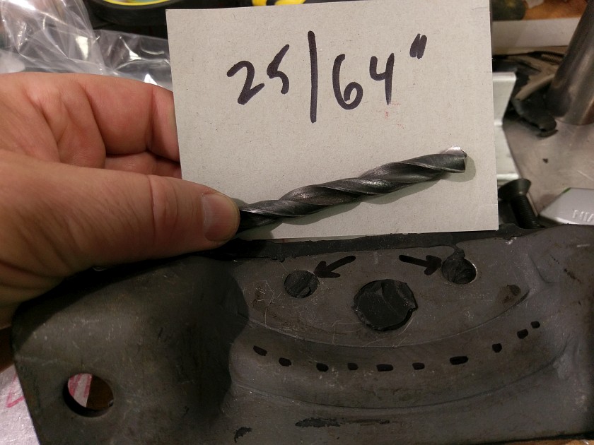
25/64" Drill Bit, or close
1" Counter Sink Tool (angle for std is 82 degrees, or metric which is 90 degress)
4 - 10mm flat head bolts 45mm in length (or equivalent length in inch 3/8" size)
4 - Locking Bolts, preferred thread interfering type not Nylock's due to heat of headers
Block of wood
Nothing special really needed, I used 10mm countersink bolts as they have a wider (90 degree)
countersink vs. The 3/8" bolts which have an 82 degree countersink. The 10mm with the 90 degree
seat will have a harder time to pull through
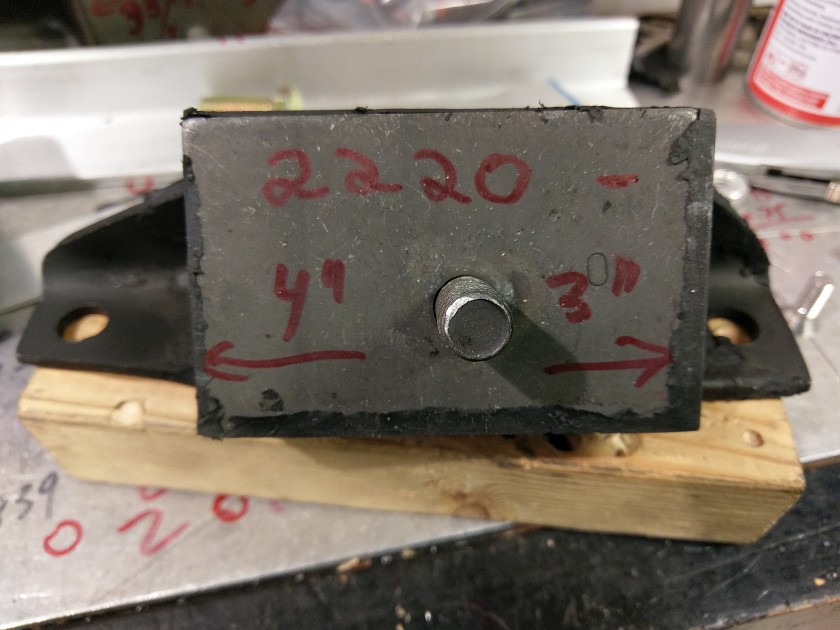
Anchor 2220 Motor Mount Top
This is the top of the mount before any work. I was looking at flipping the mounts around to see how much offset it would move the motor back so I marked some lengths on the mount. It can be ignored for this project. The Anchor 2221 is similar but the offset it a bit different.
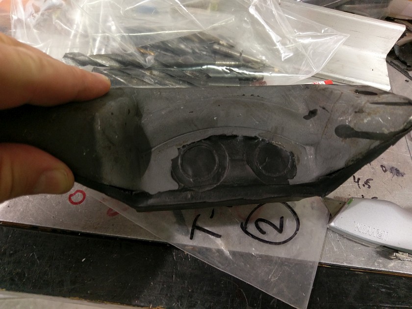
Back of Motor Mount
This is the back of the Anchor motor mount. You can see the black overflow from the filler holes when they mold the mount. You will need to remove this rubber flash to get to the 2 pre-drilled holes in the mount.
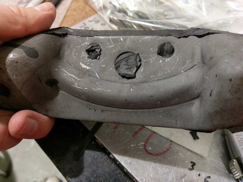
Back of Motor Mount After Cleaning
Carefully using a fresh razor knife you will need to cut away the rubber flashing on the mount. The rubber can be tough and difficult to cut so be careful with the razor. Once clean you will see 3 holes, the 2 smaller ones are what we are going to use to guide the drilling through the rubber to the flat plate side of the mount.
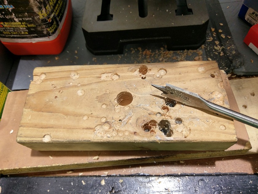
Motor Mount Drilling Jig
Here is a precision part that will help make the drilling a lot easier. Plenty of other ways to do it, this is how I did it... I used a small block of 2"x4" wood and with a paddle bit drilled a 5/8" hole though it. This will allow the engine mounts stud to drop into the hole and allow for flat and secured drilling.
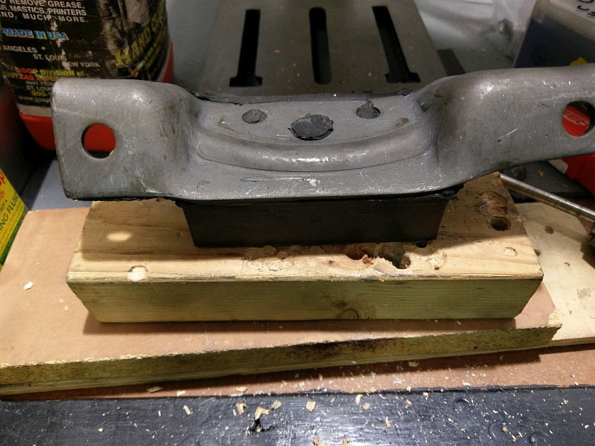
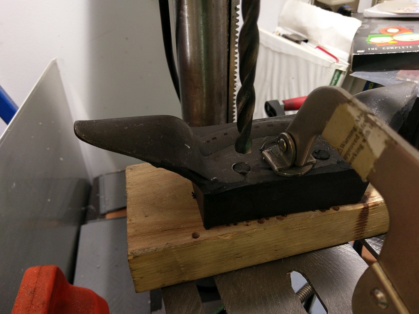
Motor Mount Drilling Jig Mounted
As you can see this makes a nice flat surface to do your drilling.
Drill Size Used
I used a 25/64" drill bit for my 10mm bolt. This size should also work with a 3/8" bolt. Use what's close, tighter better.
Drilling The Engine Mount
After thinking about the drill and the rubber mess that will ensue once I started drilling I thought it might be a good idea to use a wide mouth welding clamp (vise grip style) to hold the mount down. I didn't not make it super duper tight as that would distort the rubber and land the hole in the wrong place so I clamped it tight just until I noticed the mount to give. What could happed? Spinning mount and vise grip, all in a days work.
The drilling ended up being a non-event. The rubber cut easy with a slow speed and sharp bit. Back out often to keep things from gumming up and you will be fine.
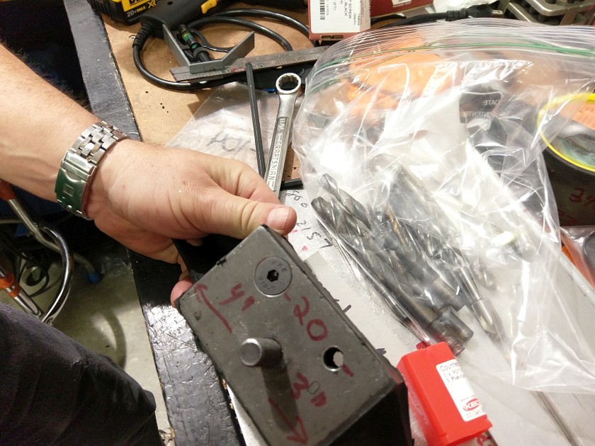
Countersinking The Bolt Holes
After drilling the 2 holes time to counter sink the holes. As mentioned I used metric 10mm x 45mm bolts. These require a 90 degree countersink. The head size was about .8" so a 1" countersink was needed. These can be a bit costly so plan on doing a set for your buddy and charge him a few bucks...
If you use a more common 3/8" countersink bolt, you will still need a 1" countersink too but the angle will be the more common 82 degree style.
Countersinking is a bit tricky unless you have some machine shop tooling mounts or get a bit creative. The problem is that to make the top surface flat for the operation you would need a 45 degree block to bolt the mount to. I didn't have anything I could rig up so I carefully clamped the mount into a large bench vise. It worked fine, but it required the use of a hand drill insted of the drill press. The large countersink was slow to cut in the steel, but after a while they all got done.
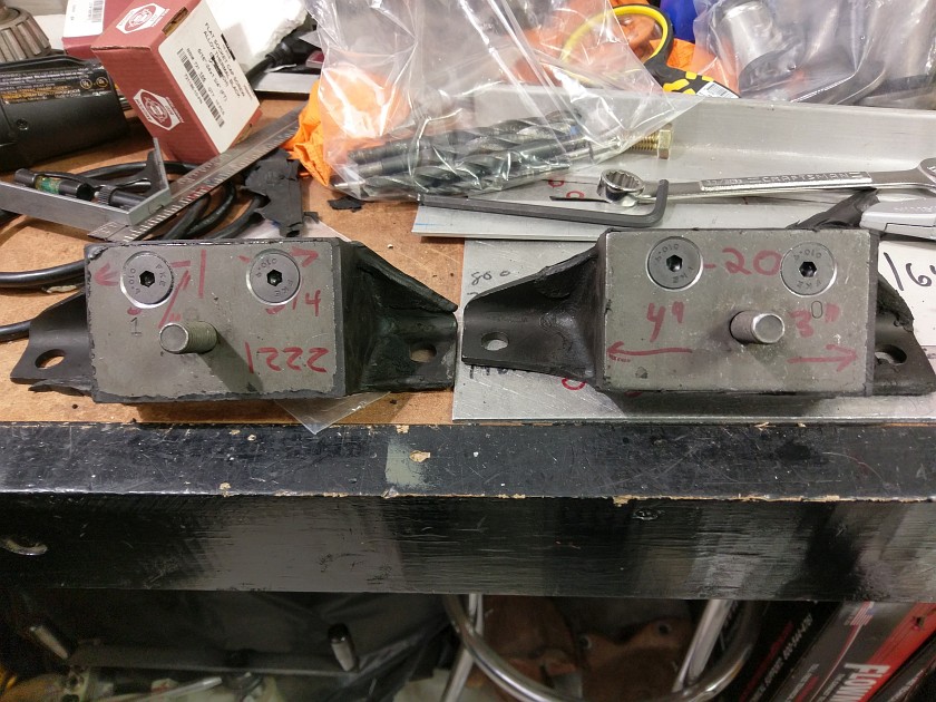
Front of the Completed Mounts
After countersink operation here is what you get. Note on the 2221 mount you can see a less accurate countersink as I didn't get it square when I started so had to make a bit bigger to make the bolt flush. Have it done by hand is not the best, but it got done. Drill press with a way to bolt the mount down would have be much easier. Still got it done in any case!
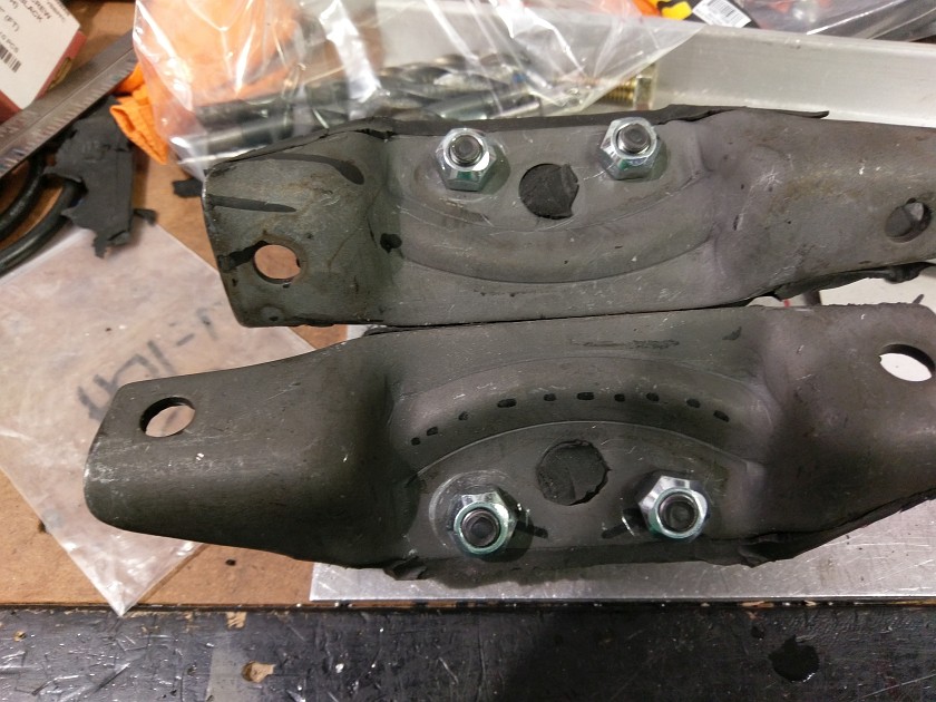
Back of the Completed Mounts
Here is the back of the mounts. The 45mm length bolts were perfect for the locking bolts. I used thread interfering bolts (jet nuts, etc). I would not use Nyloc's due to high heat on the Tiger, they might be OK on other installs. No need for washers here. Tighten up the nuts until they just touch. I don't think they need to be left loose like some other folks have done unless you want a bit more play.
My thinking is that just tightening them until they touch the metal will be good and as the engine sits on the mounts it will squish the rubber a bit and allow some movement. I looking for less movement then more so your mileage may vary in how tight you make the bolts.
Conclusion
If you can use the aftermarket urethane mounts do it, in my case they don't make ones that will work with the Tiger's style of mounting since the Tiger only uses the rubber isolator part. This is an easy project and one that will keep you from pulling the mounts apart at the track or with heavy street use.
Happy and Safe Motoring!


