Automotive Flashers and Turn Signals
On other page we did some work with the relays, and one with horns, now here is an introduction to electric cooling fans and how to safely wire them up. This is mostly targeted for vehicles that don't have any wiring yet, retrofit, race cars, etc. If you car already has an electric fan most of the hard work is done. The above view is a sampling of a few different style of electric fans (some not to scale). The fan wiring diagrams will start from simplest to more complex so you can ease into them. This is the EZ read version!
Let's jump in and take a look at some of the flashers then on to the wiring diagrams!
Click this link if you are looking for a quick introduction to Horn Relay Wiring
Click this link if you are looking for a quick introduction to Relay Wiring
Click this link if you are looking for a quick introduction to Fan Relay Wiring
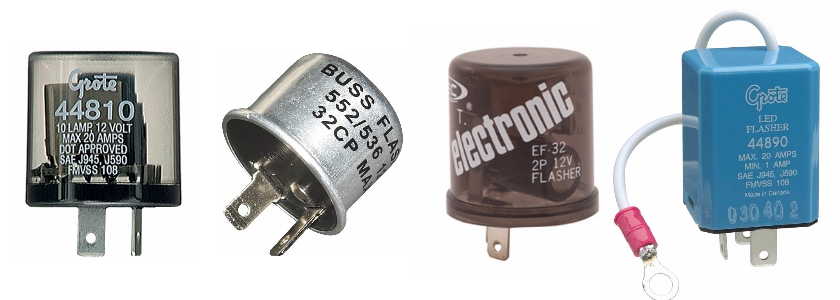
The Typical Two Prong / Terminal Automotive Flasher
This is likely the most common flasher you will find in many cars. Maybe I should say older American cars... Never the less, these are super common and for good reasons. They are cheap and work well in most cases. Auto manufacturers were about cheap and reliable and this flasher fits the bill. Newer cars will likely use some type of high tech (read expensive) electronic control unit to replace this.
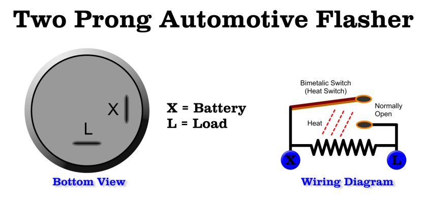
These simple flashers operate by heat. It's basically a thermostat like switch with a built in heating element.
It uses the completed circuit to heat up a small heating coil that causes a Bi-Metalic switch to open and close.
When the turn signal is on, it power completes the circuit to the turn on the lamps. Since the power is flowing only through the heating coil (high resistance) it does not light the bulbs. BUT in a short amount of time that causes the heat to rise and eventually cause the switch to close. Once it closes the heating element is shorted out and the full power goes to the lamps and turns them on. As the heating element is shorted out it starts to cool. Once it cools a bit the switch opens up again and lamps go off. This cycle goes on until the turn switch is returned to the center position.
The switch works very similarly to a waffle iron's thermostat switch that turns on and of the element as it reaches a set temperature.
Since these require a specific amount of load to work you might find that LED signal lamps will not draw enough current to cause the heating of the switch and the signals will not flash. In this case you can buy a load resistor to trick the flasher to work. Or get an electronic flasher that is designed for LED lamps.
The load on the flasher determines how much heat is generated, having too many bulbs can cause the flasher to blink unevenly (bulbs on longer then off). If you have a burnt out bulb the opposite tends to happen, since the load on the heater is less, it takes longer to heat up and the bulbs will do the opposite, they will blink unevenly with the bulbs off the majority of the time as it takes a lot longer to heat up the switch.
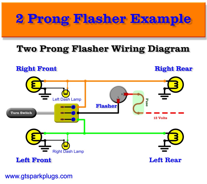
Their are only two prongs or terminals on this type of flasher. The terminals are 'X' and 'L'. The 'X' terminal is typically connected to a fused power source. The 'L' connector is typically connected to the turn switch. See below example diagrams. That's about it.
As I recall these can plug into the standard Mini-Relay socket. These come in many different styles, typically the aluminum can, some play music (I had one that played Elvis), and electronic style that are designed to operate at a blink rate regardless of load (for example LED bulbs). Their are a few flashers that require an external ground wire such as the BLUE Grote electronic flasher shown at the top of the page. I use that model and it's nice and loud.
Read on for the mystical 3 prong flasher and some example of how to wire them up as well a wiring up the emergency flasher. One thing to note that most newer cars have more complex turn signal switching then the simple switches shown in the example wiring diagrams.
Three Terminal Flasher
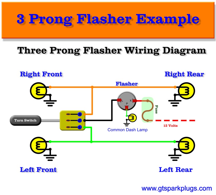
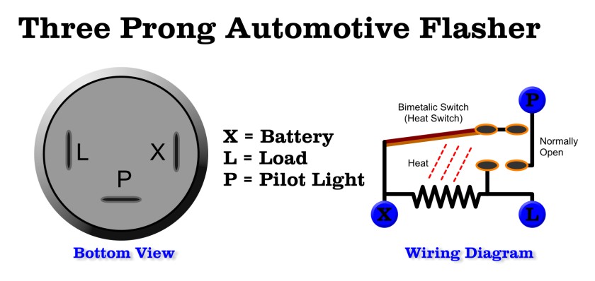
The 3 Terminal (prong as some call them) flasher is basically the same as the 2 prong. It works the same way but has an extra terminal labeled 'P'. This is simply a set of contacts that close to light up a 'single' indicator lamp on the dashboard. It can be useful if that lamp is a LED. I think this also might have application for an Emergency flasher lamp if used as a separate dedicated flasher. That being said the 'P' terminal can generally have the same functionality as connecting directly to the 'L' terminal. Remember the 'L' terminal will have SOME voltage on it at all times due to the connection of the heater, which might cause some issues if it truly needs to be off, if that's the case get a 3 terminal flasher and use the 'P' Terminal.
Note : These flasher are not pin compatible due to the orientation of the terminals.
On to the Example Flasher Circuits!
Simple Turn Signal Flasher Wiring Diagram
The above flasher wiring diagram shows how you would connect up the simplest of turn signal switch, flasher and bulbs. Note that some cars have multiple bulbs, some have single bulbs with multiple filaments so it can be a turn light and a parking light but still only use one bulb. This just shows the basics. This uses a left and right dash indicator lamps.
Onto the simple 3 terminal flasher wiring diagram
Simple 3 Terminal Turn Signal Flasher Wiring Diagram
This shows a simple wiring diagram for use of a 3 terminal flasher. The main difference is the use of a single dash board indicator lamp (no left / right indicators).
Onto the simple flasher wiring diagram with emergency flasher
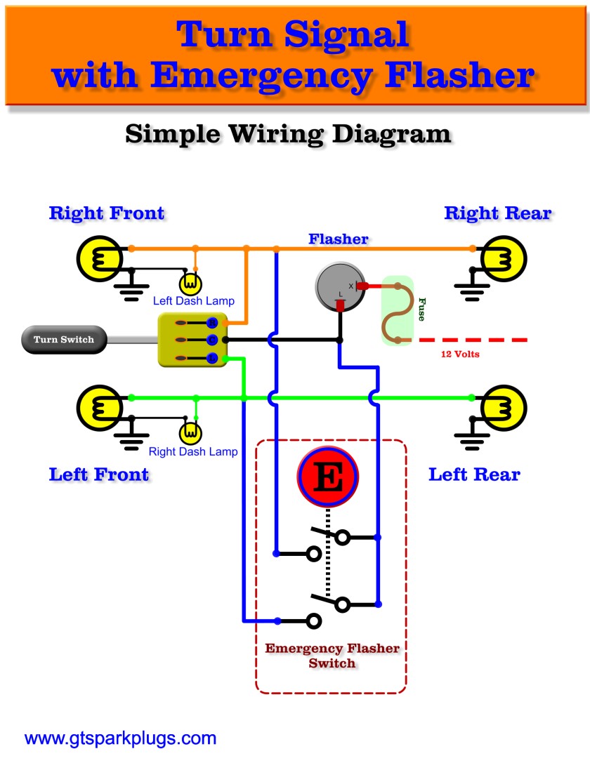
Flasher Wiring Diagram with Emergency Flasher
This is basically the 2 terminal wiring diagram with the addition of an emergency flasher switch. This will allow all indicator lamps to flash when the emergency button is pushed. The Emergency switch is basically a Single Pole Double Throw (SPDT) switch that turns on both the left and right sides at the same time. Nothing really magical here. Switching the turn switch left or right will not have any effect if the emergency flashers are activated. Other then that it's a very basic circuit to get you going and understand how this all works. Again, most auto makers have a more complicated approach to this due to the way cars are wired up these days.
Now that you can see how these simple automotive flasher work you have no excuse to finish up your wiring job. Good news is most aftermarket harnesses have this stuff all built in.
Happy Motoring!
