Safe Electric Fuel Pump Wiring


Wiring up an electric fuel pump is pretty simple, and taking a few extra precautions can make it much safer than just
hooking it up to a manual switch or ignition circuit.

Doing this properly in a race car is mandatory especially when some of these fuel pumps can drain a swimming pool in a
few seconds (obviously kidding, but you get the idea)

What does this entail? First some good practices, one is proper wiring, fusing and using the right safety circuits to keep
you and your car safe. This project will show 2 basic wiring diagrams for electric fuel pumps. One without a warning light
one with. Some parts are optional like the inertia switch, but highly recommended. 

You may ask what about the all in one switch like Holley offers? Well from the looks of things they don't use a relay with it
as the switch seems to be capable of directly controlling fuel pump, but unclear how much current it can handle reliably.
Another potential problem is you will need to route thicker wires from your battery (which may be in the rear) to the
switch and then back to the pump. Last couple of bits about this set up that bug me are their are not provisions for an
inertial switch, wait, and oh yeah it's expensive and big.

I went with the designs below, but when it comes to safety don't let me tell you what to do, but you should actually
research it and make your own choices.


Needed Supplies

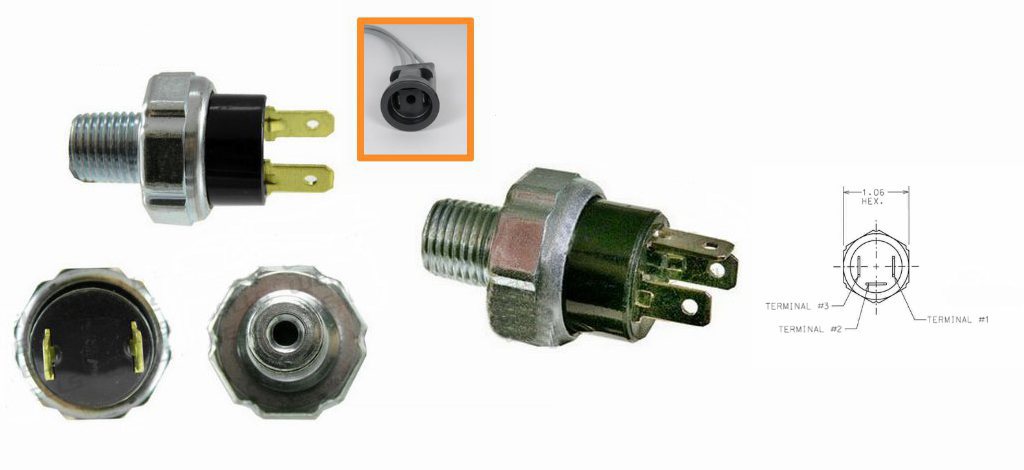
Oil Pressure Switches, (many types available common below) -
2 Terminal Basic Normally Open
PS114 2 Terminal 1/8"-27 NPT
PS113 2 Terminal 1/4"-18 NPT
3 Terminal Normally Open, and Normally Closed
PS122 3 Terminal 1/8"-27 NPT
PS118 3 Terminal 1/4"-18 NPT
2 Terminal Harness Adapters(Harder to find)
Part Number 1053 Harness Pigtail
AIRTEX/WELLS 1P1685
3 Terminal Harness Adapter (Should work with 2 Terminal)
Wells Part Number 974
GM Original Equipment PT139

Inertia Switch Available in many styles some examples -
Inertia Switch
2 Diodes 1N4007 or 1N5408 (Assortment) 1N4005-1N4007 will all work fine
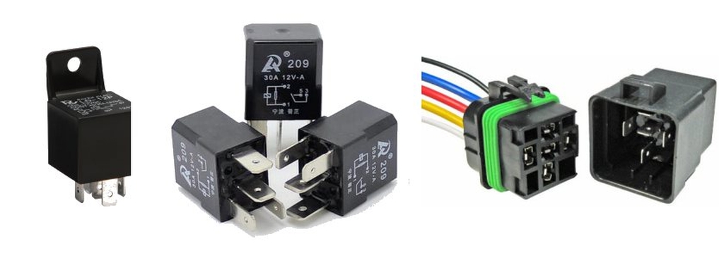
Automotive Relay and Pigtail/Harness Some waterproof, some with fuse, etc.
Side Marker Lamp or Other Indicator if building the DELUXE version. Some examples here.

Plenty of pictures below and finally the wiring diagrams!
Click for Contact Page Click for Contact Page

Oil Pressure Switches The Key!


Their are many types of oil pressure switches, most common ones are normally closed. These WON'T WORK.

These common ones will not work as we need a Normally OPEN switch that closes when oil pressure crosses some threshold. In poking around the web I found the Wells Vehicle Electronics site.
The Wells site has listings for many different style of senders. The main thing we are looking for is 'NORMALLY OPEN' or 'NO', or a combination switch that has both a NO (Normally Open) and a NC (Normally Closed).

For most common applications the 2 Prong PS113/PS114 or 3 Prong PS118/PS122 will work. These are available in either 1/8" NPT or 1/4" NPT so be sure what you order. They are available in long reach as well as a few other threads and style of connectors and fittings. Check out the Wells site for selection.

Both the PS113/PS114 and PS118/PS122 have standard spade connectors that can save some money if you don't want to spend on the waterproof harness plug. The 3 Prong PS118/PS122 can replace the PS113/PS114 as it only has an additional circuit for a warning light. Otherwise they are the same.

My preference would be to get the harness for the PS118/PS122, which is a 3 wire unit but can be used on the 2 terminal types.  If needed later if you ever want a warning light, it's ready to go with the third wire
Wells Oil Pressure Switches

Inertia Switches


This is almost always overlooked when doing an electric fuel pump, most OEM vehicles have these in some obscure place. You should have one too, but make it accessible, and if in a race car even more so.

Not sure if these would work in a off road vehicle, but I'm mainly talking road cars here. I have picked up a couple of different types of these, but now falling back on the more common OEM parts. Amazon has a few types, but hit Summit, eBay as they seem to have lower prices. These are not cheap parts, but I'll bet the cost is mostly going towards insurance if one fails...

Lastly look for the inertia switches that come with a pigtail or harness. Trying to get OEM style connectors can be a pain in the a$$ and costly so make sure you get one that comes with the wires!
Inertia Switches

Relays, Relays, Relays!


Check out the Introduction to Automotive Relays tutorial this will help you find out everything you need.

Too lazy to click but still want to know? Get a Mini style Bosch cube style relay and harness and just follow the pin numbers, you should be good. Avoid the super cheap ones as they can be problematic if you are running a lot of current (Big pump guys...)
Common Automotive Relays

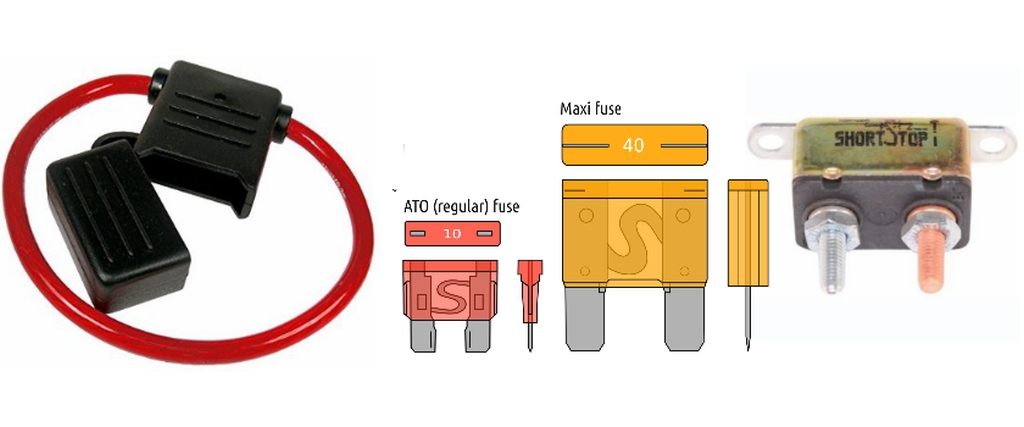
Fuses and Circuit Breakers - Use Them


Use them. If you need some guidelines look at the Headlight Relay Tutorial.  It has some guidlines for fuse selection, relays and most is applicable to fuel pumps. A very rough estimate is to do 50% more fuse rating than your current draw. If you do blow fuses on start go up a bit more as pumps tend to draw a large amount of current when power is applied (Inrush current etc.)

Last word on fuses and circuit breakers... 'USE THEM'
Layout of Fuel Pump Bracket

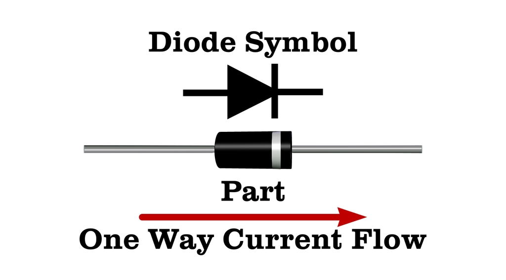
Diodes... WTF is a Diode??


WTF is a Diode you ask (skip if you already know)???

Simplest way to describe it is a diode is one way valve for electricity. We can use one to help with starting where we have no oil pressure built up yet. This can be an optional part.

If you are running a car with a carburetor you may get away without this part of the circuit. If you car builds oil pressure fast and you have fuel in the float bowls you are good. EFI cars may be a different story.

If you have an EFI car your ECU may control the fuel pump, but if going the manual route use the diode to turn on the pump once you hit the start button (or key). Diodes are inexpensive, the part numbers listed are very common.

Typically diodes have 2 leads one will have a white band next to it. Positive voltage will flow from the non-marked end towards the white band end. It will not flow in reverse. In our case we want voltage to flow to the relay when the starter switch is closed, bypassing all the safety switches so the car can start.

Once the car starts, you will have oil pressure and the pressure switch will close completing the circuit and energizing the the fuel pump. The trick is we do not want the voltage from the ignition circuit to get into the starter circuit, if it did your cars starter would never stop working. That's not what we want.
WTF is a Diode

Low Oil Pressure Indicator


You can get creative here, I have used a couple of different style of truck side markers, and may work depending on where they are mounted.

Check out some examples here for some example, look for ones that are surface mount. If using LED make sure that they are bright and you can see them in daylight. Lastly some require a special connector ensure that it's included.

If you are not sure head out to the Autozone, Pep Boys, etc and rummage through their trailering section you will find something that will work.
Low Oil Pressure Indicators

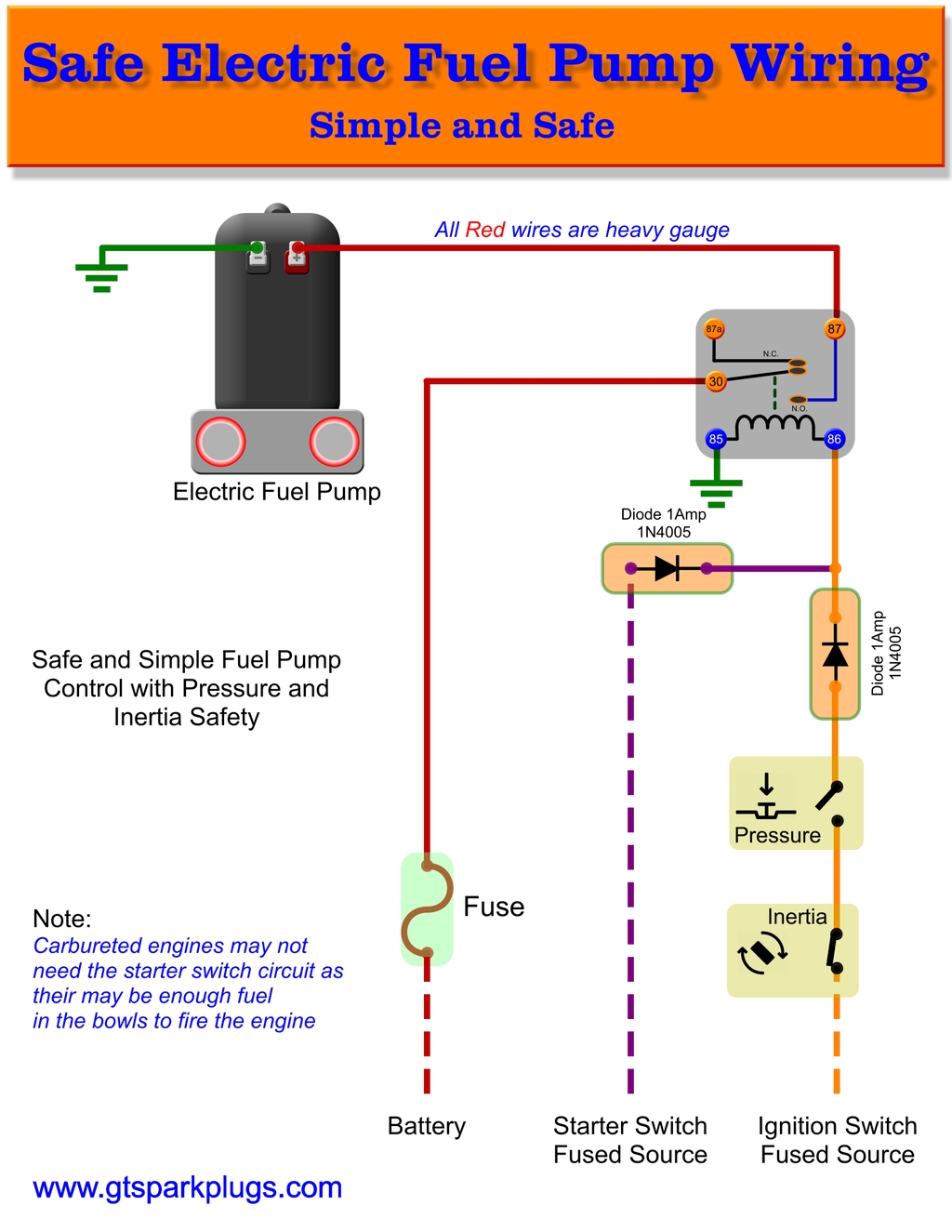
Basic Safe Electric Fuel Pump Wiring Diagram


This is the basic wiring diagram for SAFE electric fuel pump wiring. The diagram is color coded per circuit and only a few things may need to be said.

Fuel pump wiring for the RED circuit is generally going to carry a much higher current than the relay. So use a larger gauge wire for lower voltage drop.

For big pumps try 12 gauge, for smaller smaller 14 gauge. You want to limit voltage drop by using a heavy gauge wire.
Check out the Wire Voltage Drop Calculator here to help with selecting the right gauge wire

For relays and related switches 16 or 18 gauge would be OK. The fuel pump ground should be the same gauge as the positive lead if not obvious.

Basic Operation


Ignition is turned on, but no fuel pump due to the Normally Open pressure switch. Hopefully the inertial switch is OK an you are not upside down. If the inertia switch is OK, it's normally closed and will break the circuit in the event of a catastrophe.

Now you hit the start button, the voltage will pass through the diode to the relay, and the relay will close the circuit starting the fuel pump. Hopefully your car starts, and ultimately builds oil pressure which will close the oil pressure switch. This will enabling and sustain the fuel pump relay in the on position. Now you can drive away!

Once locked on by the ignition circuit the diode will BLOCK voltage back to the starter circuit.

Turing off the ignition will remove voltage from the relay, and shut off the pump. Oil pressure will be zero so the oil pressure switch will also be open circuit again.

Something bad happens


You are in a race and blow your engine and have zero oil pressure, fuel pump will stop
You are in a race and end up in a smash up, inertia swich will open, fuel pump will stop

Replace 'You are in a race' with 'I'm driving to work', or other colorful phrases. You get the idea.

That's about it. It's not hard to make it safe and reliable.  See below if you want the deluxe version!
Basic Safe Electric Fuel Pump Wiring

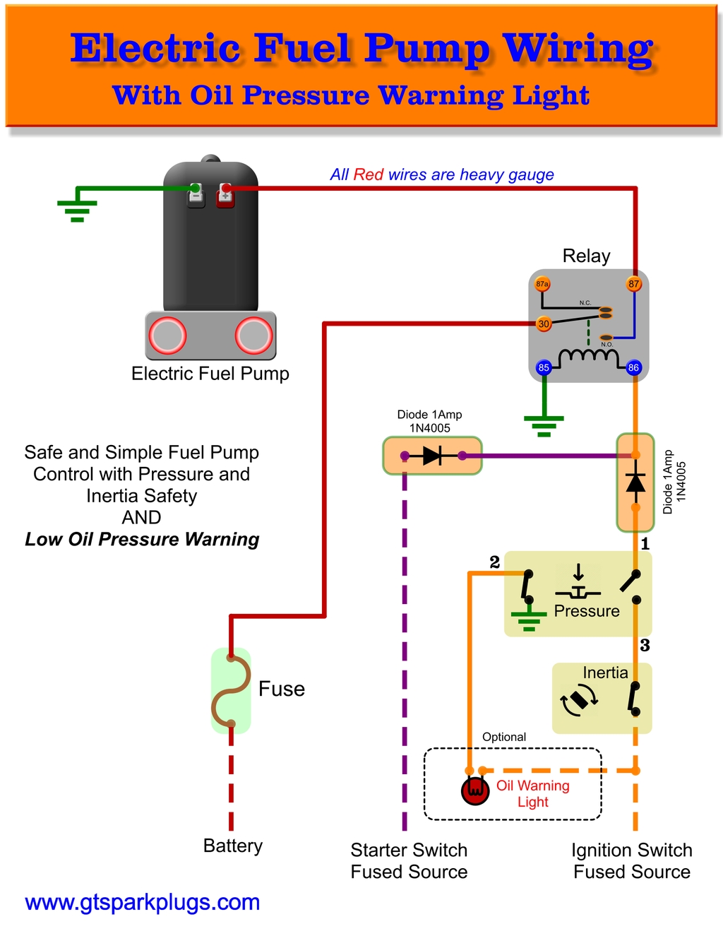
Deluxe Electric Fuel Pump Circuit with Warning Light


Deluxe Fuel Pump Wiring with Blown Engine Light circuit above

This circuit is similar to the basic wiring diagram the same except you use a different pressure switch and add a warning light that directly watches the oil pressure.

The 3 Terminal pressure switch has an extra terminal that can be used exactly like the Oil Pressure warning Light. The switch actually is 2 Switches in one. One will be used exactly like the basic wiring diagram (Terminal 1 and 3). The extra terminal (Terminal 2) will close to ground (via engine block typically and body of the switch) when pressure is lower than a couple of PSI, and will open when the engine is making oil pressure just like the old idiot lights!

This can be connected to a bulb or side marker in my examples that will shine in the face of the driver. This won't stop your motor from disaster, but will limit how bad the damage is. Also, Don't say "I have gauges and always check...", what I have to say about that "if you're watching gauges you ain't driving hard enough"

Otherwise the circuit is very similar.

Conclusion

This is a simple guide to safer wiring for your electric fuel pump. Spend some time wiring things up right and in the event of a problem it can save you a world of hurt (or fire).

Get your projects done and - Happy and SAFE motoring!

Electric Fuel Pump with Warning Light